Stage 1
A preliminary test applying a carbonyl nickel coating to several substrates was performed at CVMR Corporation in Toronto, Ontario, Canada (see Appendix 1-B in the Introduction Chapter). Zinc alloy A190, copper alloy C110 and low-carbon steel surfaces were prepared by depositing carbonyl nickel at 175 °C (347 °F). The coated specimens were subjected to various thermal exposures to increase interface bonding and to reduce residual stresses. The specimen geometries comprised planchets, approximately rectangular 51-mm x 32-mm (2-inch x 1.25-inch) coupons and 152-mm x 25-mm (6-inch x 1-inch bend specimens). Hammer impact and bend tests were performed as a preliminary assessment on how well the coatings were bonded to the substrates.
The carbonyl nickel layers were well bonded to the copper and steel substrates. Both hammer and bend tests showed no evidence of delamination or cracking. The coatings were at times well bonded to zinc (Figure 2-G-9)[63], but not consistently well attached (see Figure 2-G-10)[64]. Normal electroplating stresses are removed by annealing heat treatments. Unfortunately zinc pieces melt at a lower temperature (420 °C [790 °F]) than is needed to anneal the nickel surface layer, hence zinc cannot be effectively electroplated with nickel. The carbonyl coating process offers a potential alternative to electroplating. The carbonyl process needs further development as post- deposition annealing is needed for zinc substrates.
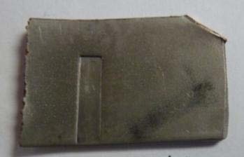
Figure 2-G-9. Carbonyl nickel-coated zinc surface after hammer indent testing with a steel punch.
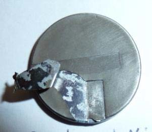
Figure 2-G-10.Carbonyl nickel-coated zinc surface after hammer indent testing.
Bend test results show no evidence of delamination or cracking for either the steel (Figures 2-G- 11 and 2-G-12) or copper (Figures 2-G-13 and 2-G-14) carbonyl nickel-coated specimens throughout the bend region. The scratches in these figures are marks from the vise used to hold the specimens during bending.
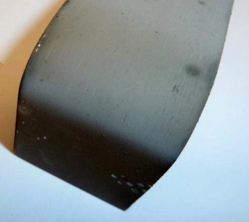
Figure 2-G-11.Carbonyl nickel-coated steel specimen after single-bend testing.
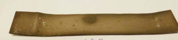
Figure 2-G-12.Carbonyl nickel-coated steel specimen bent back and forth several times.
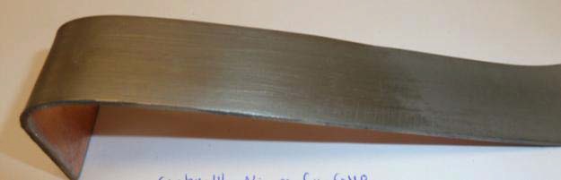
Figure 2-G-13.Single bend test of carbonyl nickel deposited on C110.
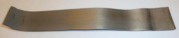
Figure 2-G-14.Carbonyl nickel deposited on C110 strip bent back and forth several times.
Stage 2
R&D on Carbonyl Ni-Coated Fe, Cu and Zn Strips.
The objective was aimed at improving the adherence of the carbonyl Ni coating to Fe, Cu and Zn substrates. The solution to the improved adherence was an annealing heat treatment after carbonyl Ni deposition: at 300 °C for the Zn strip, 350 °C for the Cu strip and 450 °C for the Fe strip. These annealing heat treatments were selected by successful bend tests on the three substrates at CVMR Corporation. Three coated and annealed Zn strips were shipped to CTC for bend testing, with the results on one specimen seen in Figure 2-G-15. All three Ni/Zn specimens were crack free showing good adherence of the coating.
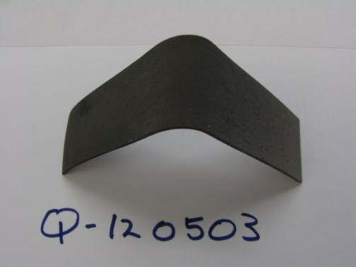
Figure 2-G-15.Bent carbonyl Ni-coated and annealed Zn alloy A190 strip.
A second objective was to improve the surface smoothness and to brighten the earlier dull carbonyl Ni coatings. To accomplish this, the strips were burnished by ball milling in zirconium oxide (ZrO2) media for 20 minutes at room temperature. The surface was brightened to a significant degree.
R&D on Prototype Tilting Carbonyl Reactor
The R&D was extended to coating of planchets in a small prototype carbonyl reactor (see Figure 2-G-16). This reactor was utilized to simulate the cyclic heating/deposition of commercial carbonyl Ni reactors that exist in the UK and Canada, which produce at the accumulated rate of nearly 200,000,000 pounds of carbonyl Ni per annum (p.a.)—far more than the capacity that would be required for US 5-cent coins. The 5,000,000 pound p.a. carbonyl reactor designed by CVMR Corporation and constructed in China is also simulated. The CVMR Corporation prototype unit used here consists of a heating chamber at one end and a deposition chamber at the other. The mechanism was designed to heat planchets to 200 °C in the heating chamber and then tilt 180 degrees to drop the planchets into the deposition chamber held at 80 °C, then re-tilt 180 degrees to return the planchets to the heating chamber. The device shown in Figure 2-G-16 is currently flipped 180 degrees by a primitive chain mechanism.
The primitive flipping sequence was practiced 6 times for a total of 10 minutes, with 1–2 seconds of deposition in each cycle. This cycle was practiced to carbonyl-Ni-coat 10 Cu planchets so the coating could be readily discerned on the reddish-gold colored copper. Deposition did occur, but further runs will be needed to optimize the cycles for larger batches of carbonyl Ni-coated Fe and Zn planchets. These planchets are not worthy of evaluation other than to show that nickel was indeed being deposited.
Figure 2-G-16.CVMR prototype carbonyl reactor.
In very recent work for another client, CVMR was able to alter processing parameters that would cause carbonyl nickel to be shiny as deposited, thereby obviating the need for burnishing. Concerns have been raised about deformation of planchets that undergo long drops that are seen in large commercial reactors. It seems that this could be moderated by designing inclined or baffled slopes in a commercial scale-up.
[63] The coating is unaffected along the edges of the hammer strike. This specimen was annealed at 240 °C (460 °F).
[64] This coating split along the edge of the indent and was readily peeled away, indicating poor adhesion. This specimen was annealed after deposition at a relatively low 200 °C (390 °F).
Source from “ALTERNATIVE METALS STUDY“, FINAL REPORT August 31, 2012,
Page 141-146, CTC Concurrent Technologies Corporation